Fire Flow Analysis
One of the goals of a water distribution system is to provide adequate capacity to fight fires. WaterCAD 2024's powerful fire flow analysis capabilities can be used to determine if the system can meet the fire flow demands while maintaining various pressure constraints. Fire flows can be computed for a single node, a group of selected nodes, or all nodes in the system. A complete fire flow analysis can comprise hundreds or thousands of individual flow solutions-one for each junction selected for the fire flow analysis.
Fire flows are computed at user-specified locations by iteratively assigning demands and computing system pressures. First the program calculates a steady-state analysis to ensure that the fire flow constraints that have been set can be met without withdrawing Fire Flow from any of the nodes. If any constraint is not met, the run will stop computing the fire flow runs and a warning message will be issued in the user notifications, either Pressure constraints violated before fire flow added. Double click for details and use Nodes to exclude if needed." and/or Velocity constraint violated before fire flow added. Double click for details.".
If the constraints are met in this initial run, the program then begins iteratively assigning the Needed Fire Flow demands at each of the nodes, and checking to ensure that the constraints are met. The program then runs another set of Steady State analyses, this time either adding the Maximum Fire Flow (as set in the Fire Flow Upper Limit input box of the Fire Flow Alternative) to whatever normal demands are required at that node, or replacing the normal demands. In either case, the program checks the residual pressure at that node, the Minimum Zone Pressure, and, if applicable, the Minimum System Pressure and maximum velocity. If the Fire Flow Upper Limit can be delivered while maintaining the various constraints, that node will satisfy the Fire Flow constraints. If one or more of the pressure constraints is not met while attempting to withdraw the Fire Flow Upper Limit, the program will iteratively assign lesser demands until it finds the maximum flow that can be provided while maintaining the pressure constraints. If a node is not providing the Fire Flow Upper Limit, it is because the Residual Pressure at that node, the Minimum Zone Pressure, or the Minimum System Pressure constraints are not met while attempting to withdraw the Fire Flow Upper Limit (or the maximum number of iterations has been reached). If a node completely fails to meet the Fire Flow constraints, it is because the network is unable to deliver the Needed Fire Flow while still meeting the pressure constraints.
After the program has gone through the above process for each node in the Fire Flow Analysis, it runs a final Steady-State calculation that does not apply Fire Flow demands to any of the junctions. This provides a baseline of calculated results that can then be compared to the Fire Flow conditions, which can be determined by viewing the results presented on the Fire Flow tab of the individual junction editors, or in the Fire Flow Tabular Report. The baseline pressures are the pressures that are modeled under the standard steady-state demand conditions in which fire flows are not exerted.
To perform a Fire Flow analysis:
- Change the Calculation Type calculation option to Fire Flow.
- Open the Alternatives manager (Cick the Analysis menu and select Alternatives).
- Double click on Base-Fire Flow to open the Fire Flow Alternative editor or create a new fire flow alternative. Create a scenario that uses the specified fire flow alternative.
- Define the needed fire flow, fire flow upper limit, pressure constraints and the fire flow nodes selection set.
- After all necessary fields have been entered, close the Fire Flow Alternative and Aternatives manager and click Compute.
- If the fire flow run has
executed successfully, open the Fire Flow Results Browser. Only the elements
that were specified in the selection set will be color coded.
If you see either this warning user notification:
Pressure constraints violated before fire flow added. Double click for details and use Nodes to exclude if needed."
or in rare cases this warning message:
Velocity constraint violated before fire flow added. Double click for details."
some actions are required to run a successfully fire flow analysis.
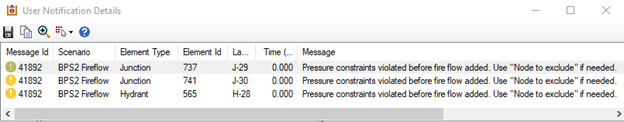
Double clicking on the message shows the user notification details windows with either the nodes or pipes violating the pressure/velocity constraints:
This message is provided for any node or pipe that fails to meet a constraint. Review those elements to determine if they are correct. Edit if necessary. If they are correct, then follow the steps below to ensure that they are excluded from follow up runs.
If the pressure results of these nodes are reasonable, select all failing nodes in the drawing by pressing the button "Select in drawing" on the user notification details windows. Right click at one of the selected nodes in the drawing, choose "Create Selection Set …" from the shown menu, enter an appropriate name for the new selection and hit the Ok button. Finally this new selection set needs to be selected in the Fire Flow Alternative dialog as "Nodes To Exclude" selection set. Note that excluding the nodes from the validation of the pressure constraints only works if either the node to exclude is not selected as fire flow node or the required individual residual pressure for this node is less than the calculated pressure from the base computation results without any fire flow demands.